🤖 Build, Learn, and Lead the Race in STEM Innovation!
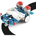
The MiOYOOW Line Following Robot Car Kit is a compact, lightweight educational robot designed for beginners to learn soldering, electronics, and sensor-based automation. Featuring photoresistor sensors for precise line tracking, it encourages hands-on STEM learning through easy assembly and customizable raceways, making it an ideal project for students and hobbyists aiming to develop practical technical skills.


| Theme | Car,Robot |
| Item Dimensions | 4 x 2.8 x 0.06 inches |
| Item Weight | 0.15 Pounds |
Trustpilot
2 weeks ago
2 days ago